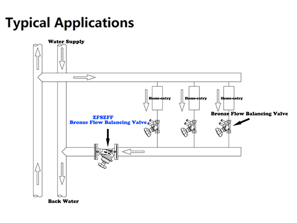
1. Installation location of Auto Balancing Valve
The auto balancing valve can be installed in the water supply pipeline or in the water return pipeline (only one in each loop). For the primary loop side of the thermal station, in order to facilitate balance debugging, it is recommended that the balance valve be installed in the water return pipeline with lower water temperature. The balance valve on the main pipe should be installed after the water supply main pipe pump (downstream of the pump) to prevent cavitation of the pump due to the low pressure before the pump (behind the valve).
2. Install on straight pipe as far as possible.
Because the balance valve has the function of flow measurement, in order to make the flow through the valve stable and ensure the measurement accuracy, the balance valve should be installed in the straight pipe section as far as possible when conditions permit.
3. Pay attention to the balance between the new system and the original system
When a new system with a balance valve is connected to the original heating (cooling) pipe network, attention must be paid to the balance of water distribution between the new system and the original system, so as to avoid the water resistance of the new system (or the reformed system) with a balance valve being higher than that of the original system and failing to reach the required water flow.
4. No need to install Stop Valves
When inspecting a loop, the balance valve on the loop can be closed. At this time, the balance valve plays the role of a cut-off valve to cut off water flow. After inspection, the balance valve can return to its original locked position. Therefore, when the balance valve is installed, the stop valve need not be installed again.
5. When adding (or canceling) loops, the system should be readjusted.
When adding (or canceling) loops in the pipeline network system, except adding (or closing) corresponding balancing valves, in principle all-new balancing valves and balancing valves in the original system loops should be re-adjusted (branch balancing valves in the original loop need not be re-adjusted).
6. Commissioning
- It is advisable to flush the system clean. Keep the valve fully open when flushing.
- If a system pressure test is required, the maximum allowed pressure PS may be exceeded by up to a maximum of 24 bar. Pressure tests must be carried out at room temperature and with the valve fully open.
7. Measuring – Pressure & Flow Rate
- Pay close attention during measurement, in case of hot media!
- Pressure test plugs are self-sealing. Unscrew the pressure test plug cap and insert the probe.
- Screw the probe ring nut to the pressure test plug.
- We recommend placing an isolation valve upstream of the probe.
- After measuring, unscrew and extract the probe. Screw the plug cap back on.
- Open the valve fully (complete anti-clockwise rotation).
- Screw the pressure gauge connected to the pressure plugs.
- Turn the hand wheel clockwise observing the pressure gauge connection. The gauge indicator is stable as long as the flow rate does not change.
- Stop turning as soon as the gauge indicator moves (differential pressure increasing).
- Take note of the differential pressure reading on the pressure gauge.
- Calculate the flow rate.
For detailed KVS and flow coefficients of auto balancing valves, please contact ZECO Valve.