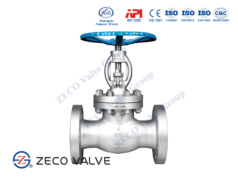
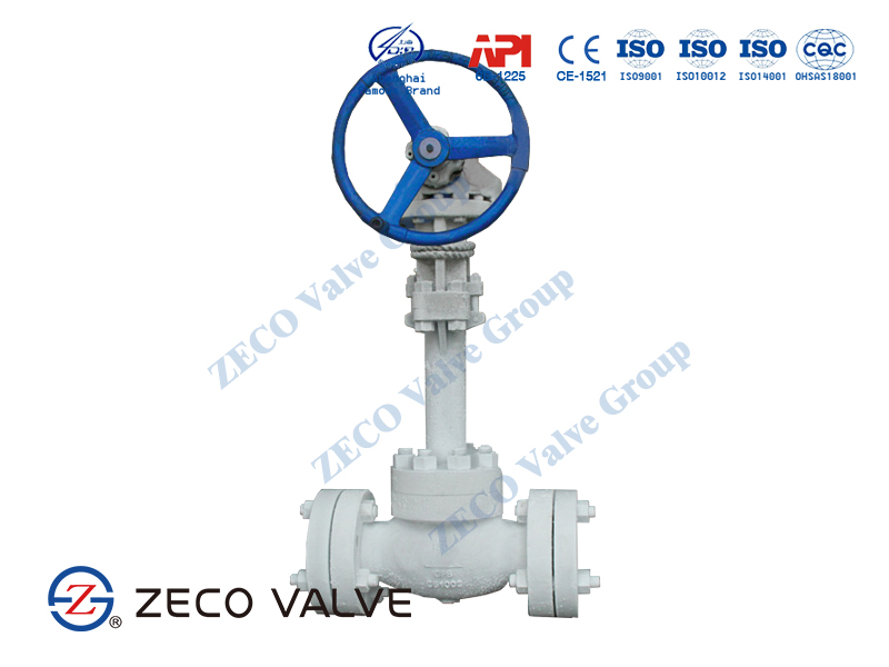
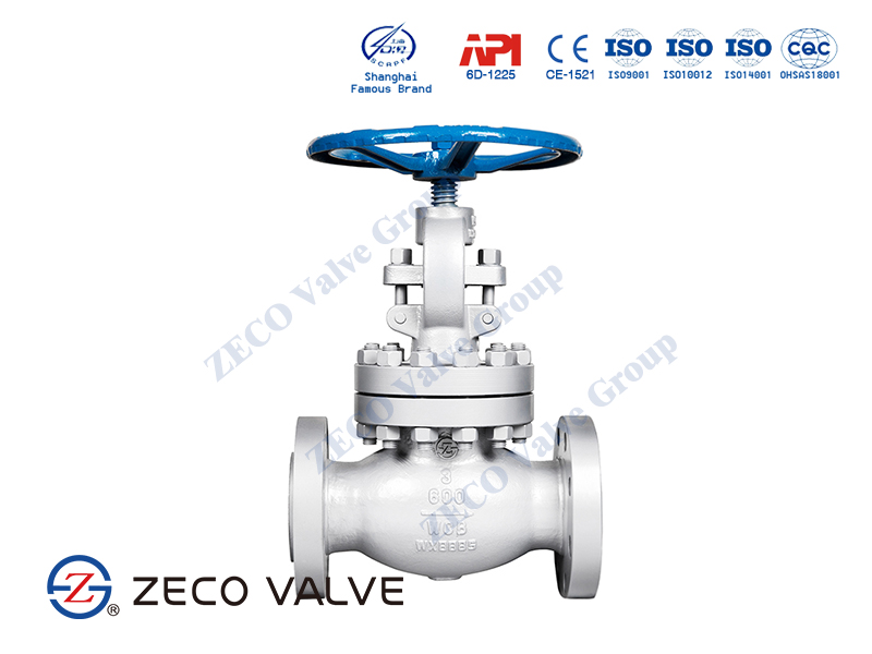
What is a Globe Valve?
Globe valves, so-called because of their outside shape, are widely used in plant piping. They are suitable for manual and automatic operation. Unlike the gate valve, the globe valve can be used for regulating flow or pressures as well as complete shutoff of flow. It may also be used sometimes as a pressure relief valve or as a check valve. Compared with a gate valve or ball valve, the globe valve has considerably higher pressure loss in the fully open position. This is because the flow of fluid changes direction as it goes through the valve. The L/D ratio for this type of valve is approximately 340. Globe valves are manufactured in sizes up to NPS 16. They are generally hand wheel–operated.
How do Globe Valves Work?
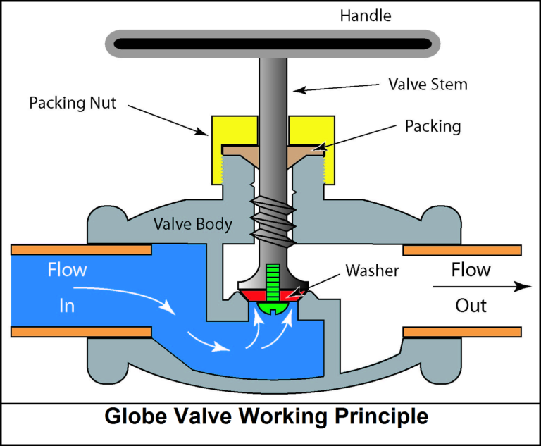
A globe valve is primarily designed to stop, start and regulate flow. It is comprised of a movable disk and a stationary ring seat in a generally spherical body. The seat of a globe valve is in the middle of and parallel to the pipe, and the opening in the seat is closed off with the disk. When the handle is turned, manually or through an actuator, a disc is lowered or raised by means of the valve stem. When the disc is fully lowered, the fluid flow is shut off. When the disc is fully raised, the fluid flow is at its maximum rate. When the disc is raised to less than the maximum level, the fluid flow is regulated in proportion to the vertical travel of the disc.
Globe Valve Types
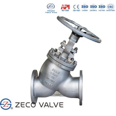
There are three primary body designs for Globe valves, namely.. Tee Pattern or Z-body, Angle Pattern, and Wye Pattern or Y-body body.
Tee Pattern Globe valve
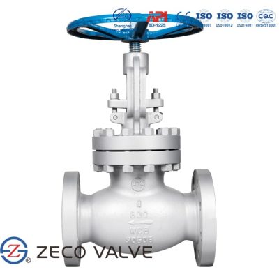
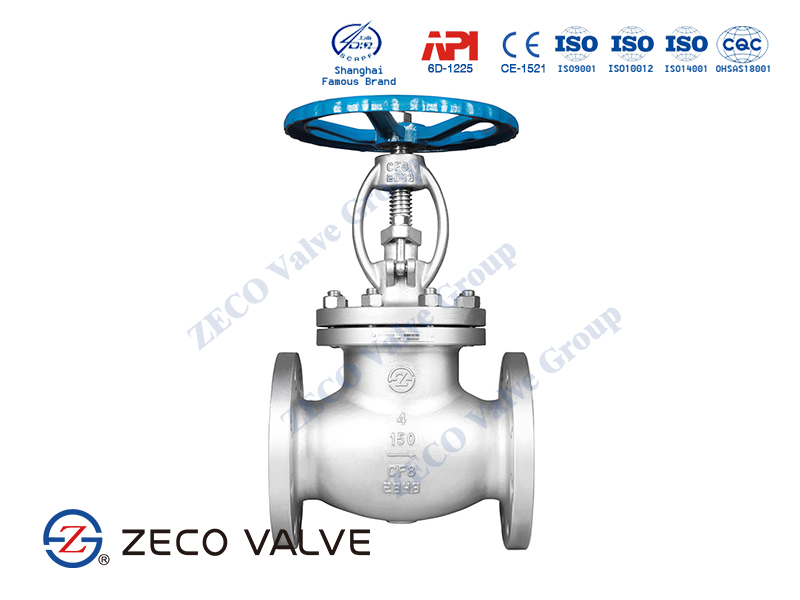
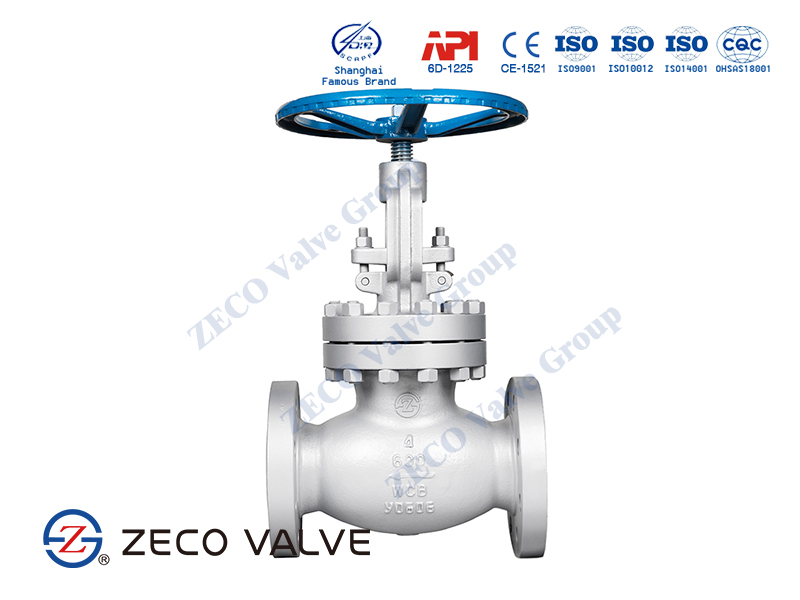
Tee Pattern Globe valve design is the most common body type, with a Z-shaped diaphragm. The horizontal setting of the seat allows the stem and disk to travel perpendicular to the horizontal line. This design has the lowest coefficient of flow and higher pressure drop. They are used in severe throttling services, such as in bypass lines around a control valve. Tee-pattern Globe valves may also be used in applications where pressure drop is not a concern and throttling is required.
Angle Pattern Globe valves
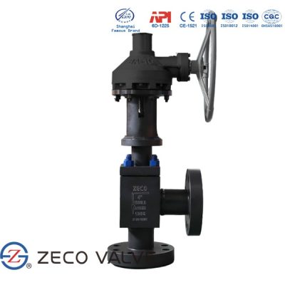
Angle Pattern Globe valves design is a modification of the basic Tee Pattern Globe valve. The ends of this Globe valve are at an angle of 90 degrees, and fluid flow occurs with a single 90 degrees turn. They have a slightly lower coefficient of flow than wye-pattern Globe valves. They are used in applications that have periods of pulsating flow because of their capability to handle the slugging effect of this type of flow.
Wye Pattern Globe valves
Wye Pattern Globe valves design is an alternative for the high pressure drop, inherent in Globe valves. The seat and stem are angled at approximately 45 degrees, which gives a straighter flowpath at full opening and offers the least resistance to flow. They can be cracked open for long periods without severe erosion. They are extensively used for throttling during seasonal or startup operations. They can be rod through to remove debris when used in drain lines that are normally closed.
Construction of Globe valves
Globe valves usually have rising stems, and the larger sizes are of the outside screw-and-yoke construction. The components of the Globe valve are similar to those of the gate valve. This type of valve has seats in a plane parallel or inclined to the line of flow.
Maintenance of Globe valves is relatively easy, as the discs and seats are readily refurbished or replaced. This makes Globe valves particularly suitable for services that require frequent valve maintenance. Where valves are operated manually, the shorter disc travel offers advantages in saving operator time, especially if the valves are adjusted frequently.
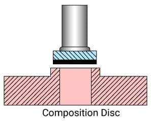
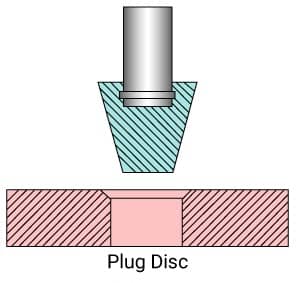
The principal variation in Globe-valve design is in the types of discs employed. Plug-type discs have a long, tapered configuration with a wide bearing surface. This type of seat provides maximum resistance to the erosive action of the fluid stream. In the composition disc, the disc has a flat face that is pressed against the seat opening like a cap. This type of seat arrangement is not as suitable for high differential pressure throttling.
In cast-iron Globe valves, discs and seat rings are usually made of bronze. In steel-Globe valves for temperatures up to 750°F (399°C), the trim is generally made of stainless steel and so provides resistance to seizing and galling. The mating faces are normally heat-treated to obtain differential hardness values. Other trim materials, including cobalt-based alloys, are also used.
The seating surface is ground to ensure full-bearing surface contact when the valve is closed. For lower pressure classes, alignment is maintained by a long disc locknut. For higher pressures, disc guides are cast into the valve body. The disc turns freely on the stem to prevent galling of the disc face and seat ring. The stem bears against a hardened thrust plate, eliminating the galling of the stem and disc at the point of contact.
Globe Valve Discs
Globe valve discs utilize three basic disc designs:
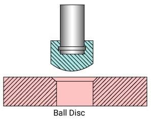
Ball Disc (Conventional Disc)
Ball disc is suitable for low temperatures and low pressures. Ideal for starting and stopping operations. Ill-suited for flow regulation.
Composition Disc (Swivel Plug)
Composition disc composites by definition consist of several components. The disc is almost always manufactured from metal whilst a non-metallic ring is mounted onto the disc to form the seating area. The non-metallic ring material is chosen to have good corrosion and erosion characteristics and may be custom made to ensure it is fit for purpose. If the non-metallic ring is chosen correctly, it should allow for better sealing. Composite discs are often employed for steam system applications.
Plug Disc
Plug discs have a long and tapered shape. The shape of the plug disc makes it much more suitable for throttling than the composite and ball disc type designs.
Globe Valve Bonnet Connection
Bonnets are other important components for the gate and globe type valves. By dismantling the bonnet, the maintenance staff has access to the internal mechanisms and can replace components like the seat, the stem, etc (trim). The Bonnet – Valve Body connection on globe valves comes in a variety of designs. Bonnets may be joined to the valve body by means of bolts, flanges, welding, or by means of a pressure-seal mechanism; the bonnet may be an integral part of the valve body. A few of the bonnet–valve body connections are detailed further.
Bolted Bonnet Connection
The bolted (also referred to as screwed-in) bonnet is one of the simplest and least expensive designs. However, the bonnet gasket must accommodate itself to rotating faces, and frequent unscrewing of the bonnet may damage the joint faces. Also, the torque required to tighten the bonnet joint becomes very large for the higher size valves. For this reason, the use of bolted bonnets is normally restricted to valve sizes not greater than NPS 3.
Welded Bonnet Connection
If the bonnet is made of a weldable material, the bonnet connection may be made entirely by welding. Welded bonnets are not only economical but also most reliable irrespective of size, operating pressure, and temperature. However, a major drawback is that access to the valve internals can be gained only by removing the weld which may cause the bonnet to distort. For this reason, welded bonnets are normally used only where the valve can be expected to remain maintenance-free for long periods, where the valve is a throw-away valve, or where the sealing reliability of the bonnet joint outweighs the difficulty of gaining access to the valve internals.
Union Ring Bonnet Connection
The bonnet may also be held to the valve body by a separate screwed union ring. This construction has the advantage of preventing any motion between the joint faces as the joint is being tightened. Repeatedly unscrewing the bonnet, therefore, cannot readily harm the joint faces. As with the screwed-in bonnet, the use of bonnets with a screwed union ring is restricted to valve sizes normally not greater than DN 80 (NPS 3).
Pressure Seal Bonnet Connection
The pressure-seal bonnet overcomes weight disadvantage by letting the fluid pressure tighten the joint. The bonnet seal, therefore, becomes tighter as the fluid pressure increases. This construction principle is frequently preferred for large valves operating at high pressures and temperatures.
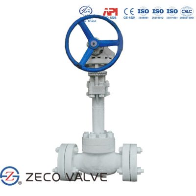
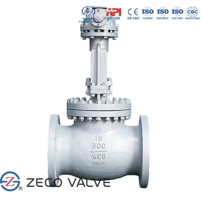
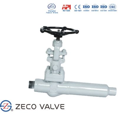
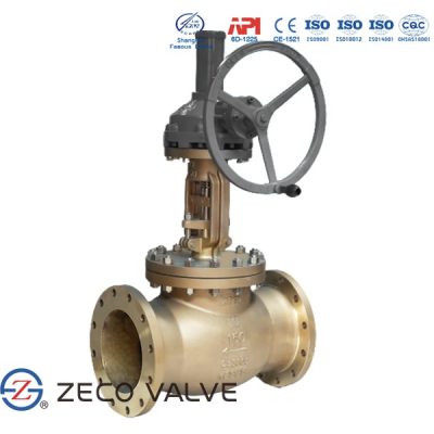
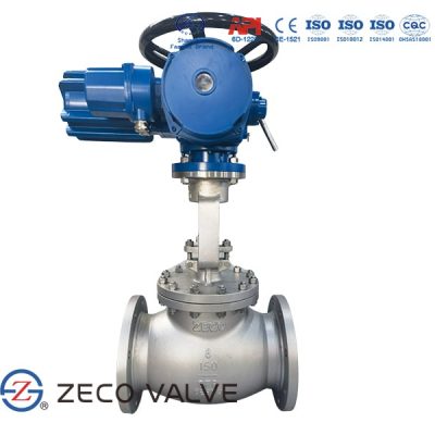
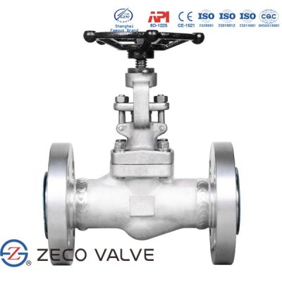
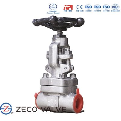
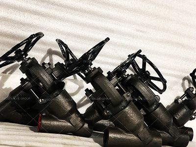
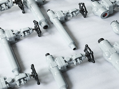
Globe Valve for Sale
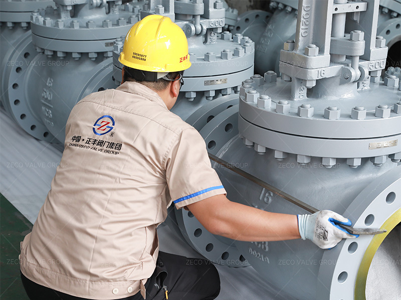
Flow Direction of Globe valves
For applications with low temperatures, Globe valves are normally installed so that the pressure is under the disc. This contributes to an easy operation and helps protect the packing.
For applications with high temperature steam service, Globe valves are installed so that the pressure is above the disk. Otherwise, the stem will contract upon cooling and tend to lift the disk off the seat
Advantages of Globe Valve
-
- Better shut off as compared to gate valve.
-
- Good for frequent operation as no fear of wear of seat and disk
-
- Easy to repair, as the seat and disk can be accessed from the valve top
-
- Fast operation compares to gate valve due to shorter stroke length
-
- Usually operated by an automatic actuator
Advantages of Globe Valve
-
- High head loss from two or more right-angle turns of flowing fluid within the valve body.
-
- Obstructions and discontinuities in the flow path leading to a high head loss.
-
- In a large high-pressure line, pulsations and impacts can damage internal trim parts.
-
- A large valve requires considerable power to open and create noise while in operation.
-
- It is heavier than other valves of the same pressure rating.
-
- Costlier compared to the gate valve.

