Brief Introduction of Hydraulic Balance System
All heating and air conditioning systems should achieve two main objectives:
- 1. Provide the required comfort;
- 2. To achieve the above objectives with minimum energy consumption.
But in fact, even the most complex control system can not bring satisfactory results, and the operation cost is high.
- 1. It’s too hot in some places and too cold in some places.
- 2. In some rooms, it is difficult to start after setting back.
- 3. Installation power can not be fully utilized.
- 4. Higher energy consumption than expected.
Common phenomena of hydraulic imbalance
1. Common phenomena of flow imbalance
The system is uneven in heat and cold:
- A. Near heat far cold (near cold far heat) when heating (cold).
- B. The water volume of some branches is too large or too small.
Variable flow system is out of order.
Load is stable, but room control valve operates frequently, resulting in frequent room temperature oscillation.
The running energy consumption of the pump is too high.
The stability time of the system is too long.
2. Common phenomena of pressure imbalance
The control valve produces noise and vibration.
Regulating valve can not be closed, and there is danger of burning valve when it is serious.
The valve weight of the control valve is too small, and the curve of the valve is deformed. The linear heat dissipation controlled system becomes the up-throwing heat dissipation controlled system.
Non-uniformity of heat and cold in the system.
Misalignment of Variable Flow System
Commonly used in variable flow system with static balance valve, even if each end has been debugged and balanced during debugging, when used in practice, when some end is adjusted or closed, the pressure difference between the other ends will change. As a result, the change of other unregulated terminal water volume will lead to imbalance, which is a dynamic imbalance phenomenon.
Load is stable, but regulator operates frequently
After the dynamic imbalance occurs, the room temperature fluctuates due to the change of water flow through the end, and the thermostat controls the regulating valve to adjust the water flow. At this time, the load of the room has not changed. The regulating action of the control valve is caused by the fluctuation of system pressure.
Variable flow system
Regulating valves are responsible for energy control, acting only when load changes, while balancing valves are responsible for pressure control and absorbing pressure fluctuations in the system.
Long time of system stability
If an air conditioning system fails to maintain a good linear relationship between the opening of the control valve and the heat dissipation of the heat dissipation equipment, it will cause frequent fluctuations in the temperature of the controlled room, and the system stability time is too long.
Noise and Vibration of Regulating Valve
According to the continuous flow equation, water has a process of acceleration and deceleration as it flows through the control valve. The corresponding dynamic pressure also has a process of increasing and decreasing. According to Bernoulli equation, the static pressure has a process of decreasing and rising. When the static pressure at a certain point drops to the vaporization pressure corresponding to the water temperature at that point, bubbles will appear at that point, and “cavitation” will occur, resulting in noise and vibration.
The greater the pressure drop of the control valve, the higher the water temperature (mainly in winter) is.
Regulating valve can not be closed, sometimes there is dangerous phenomenon of burning valve.
When some end control valves of the system are closed, the flow velocity of the main pipe decreases, so the friction resistance decreases, and the pressure difference between the two ends of the other end electric control valves increases. When the difference of closing pressure of the electric control valve is higher than that of the electric control valve, the driver of the electric control valve can not provide enough torque to close the electric control valve, resulting in the phenomenon that the valve can not be closed. At this time, the terminal is in the overcurrent state, the controller will continue to require motor action to close the valve, but the fact is not closed, the motor continues to heat, if the driver does not have overload protection function, it is easy to burn the motor.
Why is the hydraulic system balanced?
The technology of hydraulic balance in heating and air conditioning systems is the key to energy saving and improving the quality of cooling or heating.
Common problem
- 1. In the heating or air conditioning system, due to various reasons, most of the transmission loops and the cold heat source unit loop have hydraulic imbalance, so that the actual flow through the end user and the unit does not match the design flow.
- 2. Most pumps are selected too large or the pump is running at an inappropriate working point, resulting in the water system being in a large flow and small temperature difference operating conditions, the pump operating efficiency is low, and the heat transfer efficiency is low.
- 3. The room temperature of each user is inconsistent and unstable, the room temperature near the heat source is high, and the room temperature at the far heat source is low. The room temperature near the cold source is low, and the room temperature at the far cold source is high.
- 4. For heat source or cold source units, the unit does not reach its rated output, so that the number of units actually operating exceeds the number of units required by load.
Improve comfort
- Ensure that the room temperature meets the design requirements and reach the set temperature in a short time.
- Reasonable traffic distribution
- T he hydraulic balancing valve absorbs excess pressure differential and controls and sets the flow required by the system.
- Save energy and reduce operating costs
For every 1 °C decrease in temperature in an air conditioning system, energy consumption is increased by 15%.
For every 1 °C increase in temperature in a heating system, energy consumption is increased by 10%.
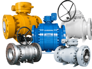
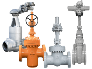
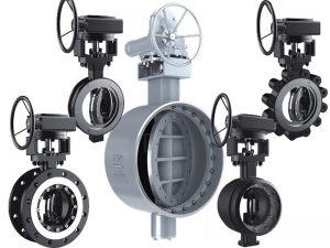
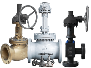
The basic concept of the valve and the classification and selection of the balance valve
Valve circulation capacity – Kv
- 1. Definition: When the pressure difference across the valve is 1 bar, the flow through the valve when the valve is fully open, in m3 / h.
- 2. Calculation:
- 3. Formula derivation:
For the regulating valve, when the valve opening degree does not change, the flow capacity of the valve does not change. The flow capacity of the valve changes only when the opening of the regulating valve changes. The relationship between the regulation valve curve and the system settling time.