


What is a Balancing Valve?
Balancing valves maintain flow conditions so that control valves function properly in HVAC systems, because unbalanced systems can produce wide temperature variations among rooms and can increase energy needs. We offer a line of balancing valves that help heating and cooling systems perform well and cost-efficiently.
How do balancing valves work?
There are many methods of regulating flow through a system, so it is difficult to explain how every balancing valve functions and also keep this article brief; however, to generalize, all balancing valves utilize some form of regulation to create constant output from a variable input. A designer can be sure that, even if turbulence or losses in pressure cause widely changing flow rate through a system, the flow rate will be constant and predictable after a balancing valve. They are analogous to resistors in an electrical circuit, where these components restrict the flow of electricity to ensure the correct voltage gets to the output. This section will explain how some common balancing valves work, and how they use mechanical properties to provide consistent flow rates.
Types of Balancing Valves
Balancing valves are available in several variations to suit different hydronic systems. Some of the most prominent types are:
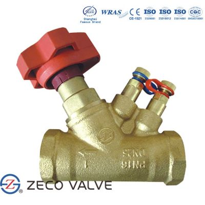
Static balancing valves
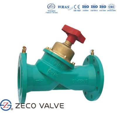
Static balancing valves also called manual balancing valves or pressure-dependent balancing valves—offer a fixed resistance to water flow. The settings for these valves are calculated before installation and then adjusted when the valves are installed in the field. Internal valve parts remain static during system operations.
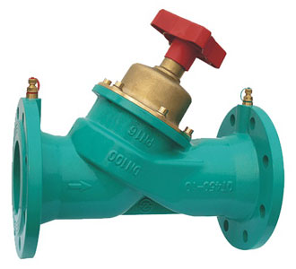
Automatic balancing valves
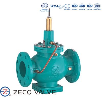
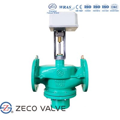
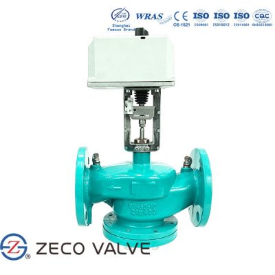
Automatic balancing valves—also known as pressure-independent balancing valves and dynamic balancing valves. These valves are designed to automatically maintain a fixed value of flow rate, despite changes in differential pressure, in order to optimize system operation. In contrast to static balancing valves, these valves have internal parts that move to compensate for changes in differential pressure, enabling them to operate more efficiently under variable load conditions.
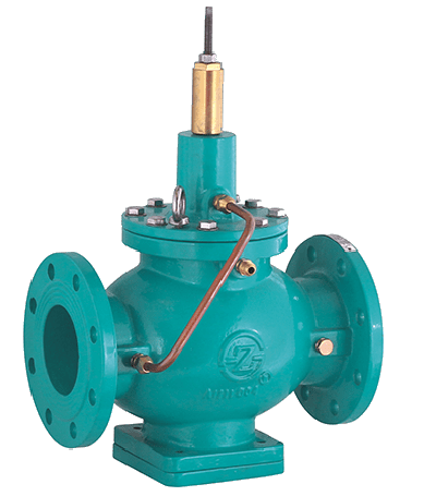
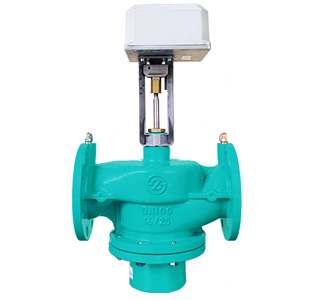
Pressure independent flow control valve
Pressure independent flow control valves are all-in-one devices that combine the capabilities of balancing valves, control valves, and differential pressure regulators. They feature built-in differential pressure regulators that automatically accommodate changes in system pressure to stabilize flow within the heating or cooling components to meet different temperature demands. Pressure-independent control valves can matched with actuators that provide remote flow control capabilities.
Advantages of balancing valves
- System accuracy can be increased
- Proper flow can be achieved in a system with the help of a balancing valve
- Dynamic system balance can be achieved
- It can save the pump energy
- It can do flow measurement and balance
- It can also detect the pressure
- These valves can be used for both the heating and cooling applications
Applications of Balancing Valves
The primary use case of balancing valves is hydronic balancing. This process refers to the optimization of water distribution within a hydronic heating or cooling system by equalizing fluid pressure. Ultimately, by achieving balance within these systems, balancing valves ensure the following:
- Correct temperature levels are reached and maintained
- Energy utilization is optimized
- Operating costs are lowered
The following points must be considered before commissioning:
- The adjustment of a valve in a sub-circuit alters the flow not only in the sub-circuit, but also in other circuits in the system. If such an adjustment reduces the flow in the sub-circuit then the flow elsewhere must increase, as the total mass flow rate is constant.
- If water flows through a pipe which has a number of branches then the percentage of the total flow in each branch remains constant irrespective of how the total mass flow alters.
- The initial objective is to obtain the same percentage of the total flow rate in each part of the system (%DFR).
- Flow is induced into less favoured circuits from favoured circuits.
- Start with the most favoured branch to induce flow to less favoured branches (greatest %DFR).
- The index circuit is that circuit displaying the lowest %DFR of the group of circuits on any one branch.
- Each circuit is balanced against the index circuit starting with the circuit next to the pump and working back to the index.
- Once all the groups of circuits within branches have been adjusted, the branch valves can be balanced as for the terminals working back towards the index.