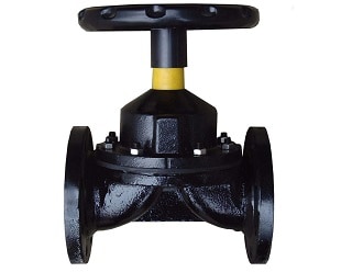
Diaphragm Valve
Diaphragm valves are in most situations, not an important consideration. But when a valve can improve your performance in downstream processes it … Read more
GET DIAPHRAGM VALVE DIAGRAM INFORMATION
Diaphragm valves get their name from a flexible disc that comes into contact with a seat at the top of the valve body to form a seal. A diaphragm is a flexible, pressure-responsive element that transmits force to open, close, or control a valve. Diaphragm valves are related to pinch valves, but use an elastomeric diaphragm, instead of an elastomeric liner in the valve body, to separate the flow stream from the closure element.

Diaphragm valves are simple in construction and operation. A valve actuator is in contact with the inner membrane (or “diaphragm”) of the valve in its open position. When the user desires the valve to be shut, the actuator is pressed and/or turned and the membrane is pushed into the edge of the solid damn, closing the valve. Certain diaphragm valves can also have half open/restricted positions where the membrane is partially closed, allowing a throttled flow through the valve. In the next section, we will examine the broad categories of diaphragm valves and where they are most useful.
The weir-type diaphragm valve is one of the most common designs available and is what is shown in Figure 2, above. The raised lip/saddle design is best suited for small flow control and is kept leak-proof thanks to the bonnet over the diaphragm and actuator. This design is optimal for dangerous or corrosive liquid and gas, as any failure with the membrane will be kept contained by this bonnet. Also, the sloped body makes this valve inherently self-draining, but this draining can happen in both valve directions which may not be optimal for some applications. The weir-type valve is mostly specified for clean, homogenous fluids, as viscous slurries and sediments may build up on either side of the saddle. They are most often found in processes such as food/chemical, gas production, corrosive, and water applications.
The straight-through diaphragm valve is structurally similar to weir-types; however, it does not contain the characteristic saddle and instead has a completely straight pathway. Their membranes are typically more flexible and allow for farther travel distance, as it must touch the very bottom of the valve. These valves must often be serviced/replaced, as their lifespan is typically less than weir-type designs due to their more flexible membranes. Straight-through diaphragm valves are used for slurries, viscous fluids, and other applications where blocking must be reduced. They are also useful for bi-directional flow regimes, as there is no saddle to impede swift changing from inlet to outlet.
The components of diaphragm valves are the following:
The bonnet serves as the top cover and is bolted to the valve body. It protects the compressor, stem, diaphragm, and other non-wetted components of the diaphragm valve.
The valve body is the component directly connected to the pipeline wherein the fluid passes. The flow area inside the valve body depends on the type of diaphragm valve.
Both the valve body and bonnet are constructed from strong, rigid, and corrosive resistant materials.
The diaphragm is made from a highly elastic polymeric disc that moves down to touch the bottom of the valve body to limit or obstruct the passage of fluid. The diaphragm lifts if the fluid flow rate is to be increased or the valve is to be fully opened. The fluid flows underneath the diaphragm. However, this component limits the valve’s operating temperature and pressure due to the diaphragm’s material and structure. It must also be replaced periodically since its mechanical properties degrade during usage.
The diaphragm isolates the non-wetted components (compressor, stem, and actuator) from the flowing media. Therefore, solids and viscous fluids are less likely to interfere with the operating mechanism of the diaphragm valve. This also protects the non-wetted components from corrosion. Conversely, the fluid in the pipeline will not be contaminated with the lubricant used in operating the valve.
Unlined or Rubber Lined Type
Fluorine Plastic Type
The compressor is a disc that lies between the valve stem and the diaphragm. It supports the diaphragm valve and distributes the forces from the stem during linear movement. The compressor design is optimized to provide better flow throttling and control.
The stem is a vertical shaft connected to the compressor that exerts linear motion to move both compressor and diaphragm, thus operating the diaphragm valve. It transmits the motion exerted by the actuator. Diaphragm valves can either have piston- or threaded-type stems. As the name implies, piston-type valves are moved by a piston assembly inside the bonnet, with the valve stem likely acting as the piston rod. This type requires linear force exerted by fluid pressure. Threaded stem valves have a matching stem nut. This type requires torque to linearly move the stem, as well as lubrication for smooth motion.
The threaded stems of diaphragm valves can have a rising or non-rising mechanism:
| Advantages | Disadvantages |
| Extremely clean | Can only be used at moderate temperatures (-60 to 450ºF) |
| Leak proof seal | Can only be used in moderate pressures (approximately 300psi) |
| Tight shut-off | Cannot be used in multi-turn operations |
| Easy maintenance | No industry standard face-to-face dimensions |
| Repairs can be made without interrupting the pipeline | The body must be made of corrosive resistant material |
| Reduce leakage to the environment |
Diaphragm valves are in most situations, not an important consideration. But when a valve can improve your performance in downstream processes it … Read more
Diaphragm valves consists of a valve body with two or more ports, a diaphragm, and a “weir or saddle” or seat upon … Read more