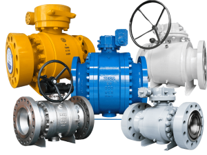
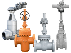
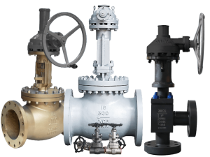
API 602 Gate Valves, Bolted Bonnet, Rising Stem, Socket Weld with 100mm Long Plain End Nipples Welded at Both Ends, PWHT.
So have you heard of PWHT? What’s PWHT?
Overview of Post Weld Heat Treatment (PWHT)
Welding is an essential part of operating and maintaining assets in the petroleum (upstream, midstream, downstream) and chemical processing industries. While it has many useful applications, the welding process can inadvertently weaken equipment by imparting residual stresses into a material, leading to reduced material properties.
In order to ensure the material strength of a part is retained after welding, a process known as Post Weld Heat Treatment (PWHT) is regularly performed. PWHT can be used to reduce residual stresses, as a method of hardness control, or even to enhance material strength.
If PWHT is performed incorrectly, or neglected altogether, residual stresses can combine with load stresses to exceed a material’s design limitations. This can lead to weld failures, higher cracking potential, and increased susceptibility to brittle fracture.
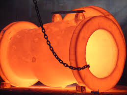
PWHT encompasses many different types of potential treatments:
Two of the most common types are post heating and stress relieving:
Post Heating:
Hydrogen induced cracking (HIC) often occurs when high levels of ambient hydrogen permeate into a material during welding. By heating the material after welding, it is possible to diffuse hydrogen from the welded area, thus preventing HIC. This process is known as post heating and should begin immediately after the weld is completed. Rather than being allowed to cool, the material needs to be heated to a certain temperature depending on the type and thickness of the material. It should be held at this temperature for a number of hours dependent on the thickness of the material.
Stress Relieving:
By the time it’s complete, the welding process can leave a large number of residual stresses in a material, which can lead to an increased potential for stress corrosion and hydrogen induced cracking. PWHT can be used to release these residual stresses and reduce this potential. This process involves heating the material to a specific temperature and then gradually cooling it.
Whether or not material should undergo PWHT depends on a number of factors, including things like its alloying system or whether it’s been subject to heat treatment previously. Certain materials can actually be damaged by PWHT, while others almost always require it.
In general, the higher the carbon content of a material, the more likely it needs PWHT after welding activities have been conducted. Similarly, the higher the alloy content and cross-sectional thickness, the more likely the material is to need PWHT.
When PWHT is required for Carbon Steel?
Post Weld Heat Treatment or PWHT of Carbon Steel must be performed after every welding in order to ensure the material strength of the part is retained. The exact criteria for PWHT of carbon steel are mentioned in the ASME BPVC code. PWHT ensures the reduction of residual stresses, controlling material hardness, and enhancement of mechanical strength.
Advantages of Post Weld Heat Treatment | Purpose of PWHT
If PWHT is neglected or performed incorrectly, the residual stresses can combine with service load stresses. The value may exceed a material’s design limitations leading to weld failures, higher cracking potential, and increased susceptibility to brittle fracture. Other benefits of PWHT are listed below:
- Improved metallurgical structure
- Improved ductility of the material
- Reduced risk of brittle fracture as ductility increases
- Relaxed thermal stress due to the redistribution of residual stresses.
- Tempered metal
- Removal of diffusible hydrogen which helps in preventing Hydrogen-Induced Cracking (HIC)
PWHT Method and Equipment
The local post-weld heat treatment of the welded joints on the pipes shall be carried out by the electric-resistance method after the completion of all welding or repairing operations.
- The resistance heater is electrically and thermally self-insulated and is built to size for each individual pipe.
- The applied voltages across the coils are either 220 or 380 volts AC depending on the power requirements.
- The power controlling panel of post-weld heat treatment is composed of:
- A temperature controller indicator and recorder of digital type.
- A potentiometer device that controls the percentage of power input to the coils.
- A switch On and Off indicator lights, input, and output terminals for power and thermocouple connection.
- Electrical power contactors of the proper rating.
- Each panel will supply a single heating station and therefore for each heating operation, one panel will be needed. Heating and cooling rates are adjusted by manual selection of the percentage of power input by means of potentiometers.
Requirements for Post Weld Heat Treatment or PWHT
Before applying for the detailed PWHT requirements and exemption in these paragraphs, satisfactory weld procedure qualifications of the welding procedures specification to be used shall be performed in accordance with all the essential variables of ASME SECTION IX including conditions of post-weld heat treatment and other restrictions listed below.
While carrying out local post-weld heat treatment, the technique of application of heat must ensure uniform temperature attainment at all points of the portion being heat treated. Care shall be taken to ensure that the width of the heated band on either side of the weld edge shall not be less than four (4) times pipe thickness or 2″ whichever is greater.
Throughout the cycle of post-weld heat treatment, the portion outside the heated band shall be suitably wrapped under insulation so as to avoid any harmful temperature gradient at the exposed surface of the pipe. For this purpose, the temperature at the exposed surface of the pipe should not be allowed to exceed 400°c.
The valves, instruments, and other special items with welding ends, shall be protected, because of the risk of damage during post-weld heat treatment.
No welding shall be performed after PWHT.
Automatic temperature recorders that have been suitably calibrated shall be employed. The calibration chart of each recorder shall be submitted to the owner prior to starting the heat treatment operations and his approval shall be obtained. Recording equipment shall be calibrated at least once every 12 months. Also, the instrument equipment (potentiometer) which is used for calibration of recorders should be supported by a related certificate.
Preparation and Attachment of Thermocouple for PWHT
After performing visual inspection and removing surface defects and temporary tack welds (if any) an adequate number of thermocouples (based on the diameter of pipes) shall be attached to the pipe directly and equally spaced location along the periphery of the pipe joint. The minimum number of thermocouples attached per joint shall be 1 for up to 3″ diameter, 2 for up to 6″ diameter, and 3 for up to 10″and 4 up to 12″diameter and above. However, the required minimum number of thermocouples to be attached can be increased if it is found necessary.
The thermocouples shall be placed on the joint and in firm contact with the pipe as near as possible to the weld area. Thermocouples should be directly tack welded to the joint or heating band jointly provided that they have a tail of the same material and an approved filler wire or electrode not larger than 2.5 mm in diameter is used for tack welding.
In order to avoid incorrect temperature readings due to direct radiation to thermocouples, it shall be protected by ceramic fiber blanked or any other suitable insulation material.
Heating resistance elements shall be laid over the attached thermocouples throughout of heating band and shall be insulated as shown in Fig. 1 below.
Insulating materials shall be mineral wool/glass wool which can overcome the temperature employed. The minimum insulation thickness shall be 50 mm. To hold the insulation material in position wire mesh shall be wrapped around and tied or tied by other suitable means.
PWHT Temperature, Time Record
The post-weld heat treatment temperature and time and its heating and cooling rates shall be recorded automatically and present the actual temperature of the weld area. Each thermocouple shall be connected to the controlling and recording instrument for each treated joint.
Heating, Holding, and Cooling in PWHT
The heating temperature above 300°c shall be recorded and the heating and cooling rate shall not be more than that specified in related WPS and standards but in no case, more than 200°c/hr, and the difference between the temperatures measured by various thermocouples shall be within the range specified.
The heat treatment socking temperature and holding time shall be as specified in related welding procedure specifications. For easy reference, the values for different types of steel are given in the following table.
The cooling down to 300°c shall be controlled cooling. Below that the cooling down to ambient temperature shall take place under insulation coating without controlling.
Few Important Notes related to PWHT
PWHT operation shall be performed only by trained personnel having a similar experience and approved by the owner.
During PWHT joints shall be protected from rain and wind by adequate rain cover and windshield.
Hardness tests after PWHT shall be performed to determine if heat treatment has been performed effectively. Normally for Carbon Steel, the maximum Brinnel Hardness is 200 HB.
Safety Precautions during PWHT
The following safety precautions shall be provided during PWHT:
Equipment and panels shall be properly earthed.
Electrical technicians shall work with proper safety wears such as rubber gloves, shoes, etc.
Only a certified electrician will work.
Joints under PWHT shall be well cordoned with red tape/red light and danger display to avoid unknown persons coming in contact with high voltage electrical connections.
An adequate platform shall be made for in situ joints to avoid fall of a person.
Based on the above, PWHT is the critical process needed for welded material, which should be paid enough attention to during production.
Related Tags :
Ten articles before and after
A brief introduction of forged steel gate valves – Zeco | API 602 forged valve manufacturer
General situation of flange forging industry – Zeco | API 602 forged valve manufacturer
How to choose the correct diameter of forged steel valves – Zeco | API 602 forged valve manufacturer
Nuclear power gate valve – part 2 – Zeco | API 602 forged valve manufacturer
Material selection of valve sealing surface – Zeco | API 602 forged valve manufacturer

