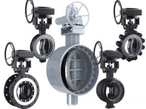
Attention should be paid to sealing direction before the installation of eccentric butterfly valve. Generally, people are accustomed to installing valves according to the flow direction of the water supply and return pipes, resulting in poor sealing performance of valves with wrong installation direction, which affects the maintenance or accident handling of the pipeline network and equipment.
Pre-Installation Information/Checklist:
- Ensure working conditions (pressure and temperature) are within the specified capacity of the product being installed.
- Make sure that the construction material of the butterfly valve is chemically compatible with the media flowing in the pipeline.
- Inspect the valve’s flange ends and the pipeline’s mating flanges to ensure the surfaces are clean and free of defects. The pipeline should also be checked for proper alignment. API butterfly valves should never be utilized to realign an existing piping system.
- The distance between pipe flanges should be checked to assure sufficient clearance for valve installation.
- The appropriate material handling equipment should be available to lift larger valves into position.
- API butterfly valves are bi-directional and may be installed with flow in either direction, vertically, or horizontally. If a choice of stem position exists, the valve should be installed with the stem in the horizontal position; this will minimize seat wear by distributing the stem and disc weight evenly. Also, if the media is abrasive, the horizontal stem position creates a self-flushing effect that will extend the service life-expectancy of the valve.
- Check that the existing pipe sizes match the inlet and outlet sizes of the unit being installed and that no interference exists. If pipeline strain is a concern with larger valves (due to weight), additional support may be necessary.
- Since the rubber seat also functions as the seal between the flanges, additional gaskets are not required.
- If possible, butterfly valves are recommended to be installed a minimum of six (6) pipe diameters from upstream components, and a minimum of four (4) pipe diameters from downstream components.
Installation Procedure:
- Install lever (for manual operated valve) or hand-wheel (for gear operated valve).
- Using lever or hand-wheel, turn (clockwise) to ensure valve is in full closed position. Disc should be aligned parallel to the ends.
- If disc is not aligned parallel to the ends, for lever style – slightly loosen top plate (by loosening 2 bolts), turn lever clockwise until disc is centered & parallel to ends, and re-tighten top plate. For gear operated valve, adjust hex nuts on side of gearbox. Fully open and close disc several times to assure proper operation. If re-alignment is necessary, repeat.
- Proceed with valve installation into piping system. Note that “wafer” style valves are placed between flanges and installed with fully threaded studs, whereas tapped “lug” style valves are installed between flanges with small cap screws on the inlet and the outlet of the valve.
- Spread the mating flanges to exceed the valve’s face-to-face dimension by 3/16” before placing the valve into position to prevent distortion and/or damage to the sealing face of the seat.
- Ensure that the pipe flange faces are clean of any foreign material such as scale, metal shavings or welding slag.
- With disc in the closed position, carefully insert between the flanges, line up, and center. Note that accurate centering between upstream and downstream pipe ends is essential for trouble-free operation of the valves.
- While gradually removing the flange spreader and verifying that the valve is centered to the flanges, secure by hand-tightening flange bolts.
- Open the valve slowly to the full open position to assure free unobstructed disc movement and that there is no contact with the piping or mating flanges. Note that disc interference may result when valves are installed in pipelines having smaller than normal inside diameters, such as heavy wall pipe, plastic-lined pipe, as-cast flanges or reducing flanges. Interference can also occur when connecting directly to a swing check or silent check. Suitable corrective measures must be taken to remove these obstructions, such as taper boring the pipe, or installing a spacer or spool piece.
- After proper operation is verified, flange bolts should then be tightened, using a star or crisscross pattern to evenly load the bolts, to the torque values shown below in table 1.
- Pressurize piping to valve and inspect for leakage. If leakage is observed, tighten bolts using cross-over pattern, increasing torque until leak stops. Note that recommended torques are made without warranty. Installer must verify proper strength bolts for applications. Bolts should be clean and un-lubricated.
I. Installation Direction of Butterfly Valve
Since the directional butterfly valves marks the sealing direction on the valve body, the direction of the arrow on the valve body of the two-way sealing butterfly valve refers to the main sealing direction. The arrow direction can also be understood in this way, that is, the arrow points to the drain end. So the supply and return water butterfly valve body arrows all point to the pressure relief end of the usual maintenance, and the eccentric butterfly valve will have better sealing performance with the action of one side medium pressure.
II. Installation Direction of Valve Shaft
All butterfly valves shall be installed in vertical pipes as far as possible, and the valve shaft should not be installed vertically but horizontally for horizontal installation. But the valve shaft can be installed at an inclined angle of no more than 45 degrees if it cannot be installed horizontally, which can minimize the deposition of solids in the fluid at the valve.
III. Other Precautions of Butterfly Valve
- Eccentric butterfly valves should generally be installed or welded under the closed state.
- The limit of the valve transmission has been adjusted before leaving the factory, so do not remove the transmission at will. If the transmission must be removed, the limit must be readjusted after resumption of installation, and poor adjustment will affect valve leakage and life.
- During butterfly valve welding, the grounding wire of the electric welding machine must be lapped on the steel pipe of the welding joint on the same side to prevent the current from passing through the valve body and burning the sealing surface.
- When installing the welding valve riser, water with a height of no less than 10mm should be injected above the closed valve plate. And wet cloth should be wrapped on the valve when welding valve is installed horizontally.
- Carefully clean the dirt on the eccentric butterfly valve after installation, and carry out 2 to 3 times of complete switching test to check whether the valve can work normally.
Wafer Type Butterfly Valve Installation
The wafer type butterfly valve is one of the most common types of valves in industrial pipelines. The structure of the wafer type butterfly valve itself is relatively small. Just put the butterfly valve in the middle of the flanges at the two ends of the pipeline, and use the double stud bolts to pass through the pipeline flanges and pairs. Clip-on butterfly valves lock the fluid medium in the line. Wafer-type butterfly valves are especially suitable for places where space is limited or where the distance between pipes is short. When the butterfly valve is in the fully open position, the thickness of the butterfly plate is the only resistance when the medium flows through the valve body, so the pressure drop generated by the valve is very low. Small, so it has better flow control characteristics.
First, the clip-type butterfly valve before installation instructions:
- Before the installation starts, remove any foreign matter on the piping with air spray and clean the inner surface of the piping with clean water.
- Carefully check whether the valve usage is in line with its performance specifications; (temperature, pressure)
- Check the valve channel and the sealing surface for debris, and remove it in time;
- After the box is opened, the valve must be installed in time. Do not loosen any fastening screws or nuts on the valve.
- Clip type butterfly valve must use a special butterfly valve flange.
- Electric butterfly valve can be installed on any angle of the pipeline, for the convenience of maintenance is not recommended to install the inverted.
- The butterfly valve flange must be installed to ensure that the flange surface and the sealing rubber center, the screw is tightened evenly, the sealing surface must be complete; if there is uneven screw tightening, there will be rubber protruding stuck disc, or top Live butterfly plate leaks at the stem.
Second, the clip type butterfly valve installation steps:
The correct installation of the wafer type butterfly valve relates to the degree of sealing of the butterfly valve and the possibility of leakage and other issues, including the safety in operating conditions. The user should understand the installation process.
- As shown, place the valve between the pre-installed two flanges and note that the bolt holes are aligned.
2. Gently insert the four pairs of bolts and nuts into the flange hole and tighten the nut slightly to correct the flatness of the flange surface;

3. The use of spot welding flange fixed on the pipe;
4. Remove the valve;

5. The flange is completely welded and fixed on the pipe;
6. After the weld is cooled, install the valve. Ensure that the valve has enough space in the flange to prevent the valve from being damaged, and to ensure that the valve plate has a certain degree of opening;

7. Correct the valve position and tighten the four pairs of bolts (be careful not to overtighten);
8. Open the valve to ensure that the valve plate can be opened and closed freely, and then make the valve plate slightly open;

9. Cross-equalization tighten all nuts;
10. Confirm once again that the valve can be opened and closed freely. Note: Make sure that the valve plate does not touch the pipe.

The installation of the wafer type butterfly valve must first be laid flat before installation. Remember that it cannot be bumped freely. After it is pulled into the installed length during installation, it is not possible to design the pipeline in the field without special permission. Feel free to disassemble the clip-on butterfly valve. This is what we need to know before installing. At the same time, we also need to know that the clip-on butterfly valve can be installed in any position, but after the installation of the clip-on butterfly valve, it is necessary to lay the butterfly valve along the line and make a bracket for the clip-on butterfly valve. Once the bracket is made, it is used. It is strictly forbidden to remove the bracket.

