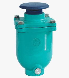
Single Orifice Air Release Valve
Description
What Causes Air in Water Pipes?
Air and vacuum formed in water mains may lead to serious operating problems and even some dramatic consequences. Air can enter piping systems in several ways:
-
- Empty Pipelines
-
- Pipelines not in operation are occupied with air. Most of it is evacuated during startup, but some air pockets can remain in the system.
-
- Empty Pipelines
-
- Air in The Fluid
-
- Depending on the temperature and pressure, liquids like water can contain trapped or dissolved air. During fluid flow, it separates from the liquid and can become trapped at the system’s high points. Also, in pipelines conveying sewage, the liquid waste can undergo chemical reactions and evolve into gases that can get trapped in the wastewater system.
-
- Air in The Fluid
-
- Mechanical Equipment
-
- Air can also get into the pipeline through mechanical systems like pumps, pipe joints, valves, etc. Leaks or faulty seals in these components can lead to air infiltrating the piping system
-
- Mechanical Equipment
How does a Vacuum Form in a Pipe?
Vacuums in pipelines occur when the pressure in the pipeline drops below the atmospheric pressure. Vacuums can appear due to sudden changes in the velocity of the flowing fluid. For example:
-
- When the pumps are switched off too fast
-
- When the valves are suddenly closed
-
- Emptying line sections of the pipeline in a wrong way
What is a Single Orifice Air Release Valve?
A Single Orifice Air Valve sometimes referred to as a “small orifice” valve, will continuously release accumulated air during system operation. As air from the pipeline enters the valve, it displaces the water, allowing the float to drop. The air is then released into the atmosphere through a small orifice. As the air is vented it is replaced. An added benefit of an Air/Vacuum Valve is its ability to provide pipeline vacuum protection. If a negative pressure develops, the air release valve will open, admitting air into the line, and reducing the potential for surges related to column separation and possible pipeline collapse.
Main Components of Single Orifice Air Release Valves
-
- Valve body
-
- The unique ductile Iron valve body is compact and houses the inner floats and upper mechanism. The body is designed so that the inlet is completely free of float guides, therefore enabling butterfly valves to be used directly under the air valve without impacting performance. Each valve body has a lower 316SS grade tamper-proof drain valve enabling the valve to be drained and tested quickly and safely.
-
- Valve body
-
- Inner float assemblies
-
- The inner floats are all manufactured from bar-stock polypropylene which ensures they cannot ever change their mass or shape. The floats are all guided and kept square to the body by the four guide ribs on the valve body ensuring they cannot get blown offset to the side.
-
- Inner float assemblies
Three Floats Assist in Producing the Three-General Functions
-
- Large orifice float
-
- This enables air inflow and discharges during filling and drainage.
-
- Large orifice float
-
- Small orifice float
-
- The small orifice float houses the nozzle subset, ensuring that the valve automatically releases any entrapped air when the pipe is full, and an air pocket presents itself into the valve.
-
- Small orifice float
-
- RFP upper float
-
- During pipe filling, this float will remain open to fill the pipe at a controlled rate. If the exit flow rate exceeds a safe working rate, it immediately rises and chokes the air discharge to a safe operating rate, avoiding the water hammer.
-
- RFP upper float
-
- Upper seat
-
- The 316S grade stainless steel seat cleverly houses the O rings that make the seal between the seat float.
-
- Upper seat
-
- Mesh outlet and cover
-
- The valve has a stainless-steel mesh that prevents any possibility of external contaminates fowling the inner floats and keeps vermin and spiders away from the underside of the cover. The ductile cover is robust and keeps any direct sunlight away from the floats and is strong enough to be stood on if fitted inside a valve pit.
-
- Mesh outlet and cover
Features of Single Orifice Air Release Valve
While Air/Vacuum Valves will exhaust large quantities of air upon start-up, it should be remembered that they will not continuously release air during system operation. For this function, a single orifice air valve is also required.
The function of a Single orifice air valve is to allow air to be expelled from the system during filling and to admit air into the system whenever sub-atmospheric pressure occurs. When water enters the valve body the float buoyancy lifts it onto the seat and the resultant rise in system pressure ensures a tight seal, with line pressure holding the float on the seat. In the event of air entering the valve while the line is still positively charged, the valve remains shut. In the event of sub-atmospheric pressure in the system, water is drawn from the body and the float drops from the seat to admit air into the system.
Single Orifice Air Release Valve Working Principle

Automatic air release valves are installed at the highest points in a pipeline where air naturally collects. Air bubbles enter the valve and displace the liquid inside, lowering the liquid level. When the level drops to where it no longer buoys the float, the float drops. This motion pulls the seat away from the orifice, triggering the valve to open and vent the accumulated air into the atmosphere.
As the air is vented, liquid re-enters the valve, once again buoying the float, lifting it until the seat presses against the orifice, closing the valve. This cycle automatically repeats as often as necessary to maintain an air-free system.
Proper installation is critical to the operation of air release valves. Because these valves are designed to release air from the piping system, they should be placed where the air is most likely to collect. Install them at system high points in the vertical position with the inlet down. Remember to add a shut-off valve below the valve in the event servicing is required.
Single Orifice Air Release Valve Installation and Commissioning

Choosing the right location for the installation of an air valve is very important. To obtain maximum efficiency, the air valves are placed at strategic locations on the pipeline’s run. For proper aeration and ventilation of water and wastewater systems, air valves are required at the following points:
-
- Maximum High Points
-
- Air bubbles accumulate and form air pockets that get stuck at the highest points in the system. Placing air valves here helps ventilate the air pockets out to the atmosphere. Valve Required: Air release valve/combination valve.
-
- Maximum High Points
-
- Temporary High Points
-
- Local high points can also serve as an accumulation spot for air bubbles. An air valve here vents the bubbles out to the atmosphere. Valve Required: Air release valve/combination valve.
-
- Temporary High Points
-
- Long Rising or Falling Pipe Sections
-
- Dislodged air pockets can flow downstream and form larger air pockets at the top section of the pipe. Also, rapid flow in downward sloping pipe sections can form a vacuum. As a rule of thumb, air release valves and air vacuum valves should be installed every 800m on long pipe runs to properly vent and draw air into the system.
-
- Long Rising or Falling Pipe Sections
-
- Long Rising or Falling Pipe Sections
-
- Dislodged air pockets can flow downstream and form larger air pockets at the top section of the pipe. Also, rapid flow in downward sloping pipe sections can form a vacuum. As a rule of thumb, air release valves and air vacuum valves should be installed every 800m on long pipe runs to properly vent and draw air into the system.
-
- Long Rising or Falling Pipe Sections
-
- After Fast Closing Valves
-
- When valves are suddenly shut off, vacuums can form downstream from the valve due to the momentum of the flow. For the proper functioning of the pipe, the negative pressure needs to be relieved by admitting air into the pipe.
-
- After Fast Closing Valves
-
- After Flow Throttling / Boosting Devices
-
- After flow throttling devices like turbines or control valves, the pressure and velocity differences can lead to the formation of a vacuum. Air vacuum valves are needed close to these devices to draw air into the system Flow boosting devices like pumps and reduced pipe sections also draw air bubbles into the flow. Air release valves need to be installed after these devices to vent these air pockets.
-
- After Flow Throttling / Boosting Devices
Finally, always install your air valves at accessible, well-ventilated locations. This ensures they always have enough air to draw into the systems, and the air expelled has a route out. Also, it makes it easier to reach the valves for maintenance.
Single Orifice Air Release Valve Material and Standard
-
- Size Range: 3/4″~2″
-
- Pressure Rating: 10bar ~ 25bar
-
- Face to Face Dimensions: EN 558-1, ASME B 16.10
-
- Flange End Dimension: BS 21
-
- Coating: Fusion Bonded Epoxy Coating
-
- Inspection and Test: ISO 5208 / EN 12226-2
| Part | Material | Standard |
| Body | Ductile Iron | EN 1563/DIN 1693 |
| Bonnet | Ductile Iron | EN 1563/DIN 1693 |
| Exhaust Hood | EPDM / NBR | ISO 4633 |
| Float Ball | Stainless Steel 431 | EN10088-1/ASTM A959 |
| Piston Rack | Stainless Steel 431 | EN10088-1/ASTM A959 |
| Tank | EPDM / NBR | ISO 4633 |