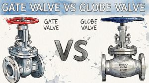
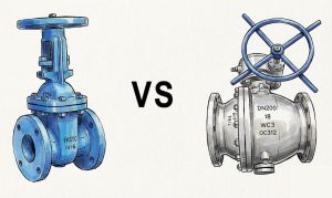
What is a Gate Valve?
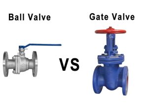
Gate valve is a gate with opening and closing parts. The moving direction of the gate valve is perpendicular to the direction of the fluid. the gate valve can only be fully opened and closed. The parameters of the gate valve are different, usually 5 degrees. When the medium temperature is not high, it is 2 degrees 52′. Improve its technicality and make up for the deviation caused by the angle of sealing surface in the process of processing. This kind of gate is called the elastic gate.
Working Principle of Gate Valve
Gate valve‘s opening and closing parts are gates, whose moving direction is perpendicular to the direction of the fluid. the gate valve can only be fully opened and closed, and can not be adjusted and throttled. The gate has two sealing surfaces. The two sealing surfaces of the most commonly used mode gate valves form wedges. The wedge angle varies with the valve parameters, usually 5 degrees, and the medium temperature is 2 degrees 52’. A wedge gate valve gate can be made into a whole, called a rigid gate; it can also be made into a gate that can produce slight deformation to improve its workability and make up for the deviation of sealing surface angle in the process of processing. This kind of gate is called the elastic gate. When the gate valve closes, the sealing surface can be sealed only by the medium pressure, that is to say, the sealing surface of the gate can be pressed to the seat on the other side to ensure the sealing surface, is self-sealing. Most gate valves are forced to seal, that is, when the valve closes, the gate must be forced to the seat by an external force to ensure the sealing of the sealing surface. The Gate valve’s gate moves in a straight line with the stem. It is called the lift gate valve, or open gate valve. Usually, there are trapezoidal threads on the lifting rod. Through the nut at the top of the valve and the guide groove on the valve body, the rotary motion is changed into linear motion, that is to say, the operating torque is changed into the operating thrust. When opening the valve, when the gate lifting height is equal to 1:1 time the valve diameter, the flow passage is completely open, but when running, this position can not be monitored. In practical use, the vertex of the valve stem is used as the sign, that is, the position of the valve stem that is not moving is used as its fully open position. To consider the locking phenomenon of temperature change, the valve is usually opened to the vertex position and reversed to 1/2-1 turn as the position of the fully open valve. Therefore, the fully open position of the valve is determined by the position of the gate, that is, the stroke. Some gate valves, stem nuts set on the gate plate, hand wheel rotation to drive the rotation of the valve stem, and make the gate lift, this valve is called rotary bar gate valve, or hidden bar gate valve.
Components of Gate Valve
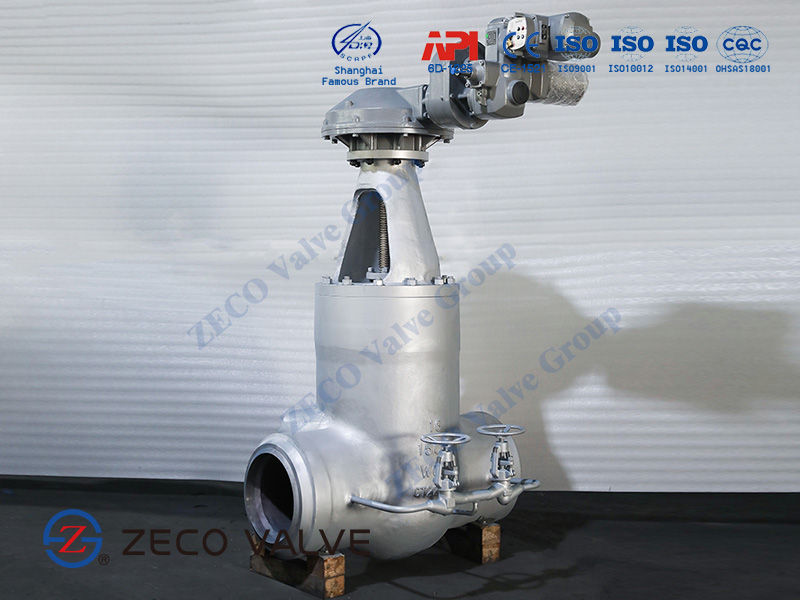
A gate valve’s vital components are the body, gate, seat, stem, bonnet, and actuator. Gate valves may have flanged ends drilled in accordance with pipeline-compatible flange dimensions requirements. Cast iron, cast carbon steel, ductile iron, gunmetal, stainless steel, alloy steels, and forged steels are common materials for gate valves. In the following, each part of the gate valve that is mentioned above is fully described.
Gate
The gate is available in a variety of designs and technologies to ensure that it provides good sealing for a number of applications; however, it can be generally classified as parallel or wedge-shaped. Parallel gates include parallel slide gates, slab gates, and parallel expanding gates. Knife gates are also another type of gate valve whose structure is very similar to wedge valves. In the following, these types are introduced.
Wedge Gates
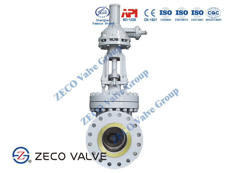
Wedge type gate valves have a wedge-shaped disc that is seated against two inclined seats. Solid wedges are utilized in applications where there is a high flow or turbulence, such as steam service. Moreover, vibration and chatter are significantly reduced due to the solid structure. In addition to the primary force provided by fluid pressure, the tightening of the stem creates a significant wedging force on the seats, which aids in sealing. Due to reduced rubbing on the seats, the wedge-shaped gate does not stick to the seat in the event of high fluid differential pressure. Hence, it also has a longer lifespan. Split wedge discs are more flexible and can be employed in situations where pipeline strains may cause valve seats to distort.
Parallel Slide Gates
Gate valves can also be found in a parallel configuration, with the gate flat and the seat parallel. Parallel gate valves provide a tight seal by utilizing line pressure. Flat gates are made up of two parts with a spring in the middle. For better sealing, the spring pushes the parts closer to the seats. Parallel gate valves have a safety advantage in higher temperature situations due to their inherent design. In wedge-shaped gate valves, an additional compression force on the seats can cause thermal binding and restricted valve opening due to expansion. Furthermore, because parallel gates have no wedging action, closing torques are reduced, resulting in smaller, less expensive actuators or less manual effort. Parallel gates keep dirt off the seating surfaces since they slide into place.
Slab Gates
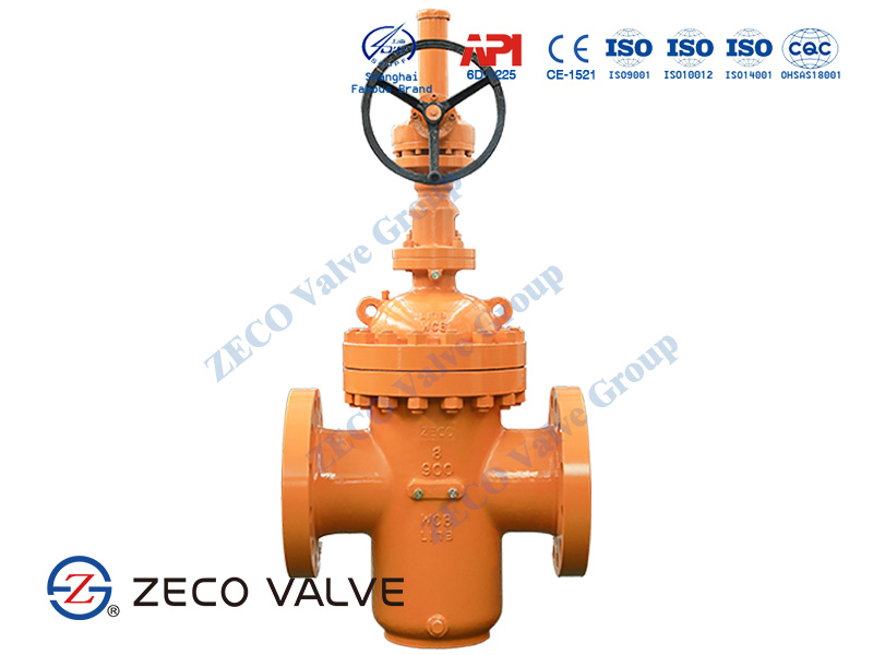
Slab gates, known as through-conduit gate valves, are single-piece gates that contain a bore-size hole in the middle. In the open position, the bore is aligned with the two-seat rings. This alignment creates a smooth, turbulence-free flow. This unique design provides for minimal pressure loss on the system and is ideal for transporting crude oil and natural gas liquids. The valve seats are still clean. The disc cavity, on the other hand, can catch foreign particles. As a result, the cavity usually contains a built-in plug for removing the accumulated foreign material during maintenance.
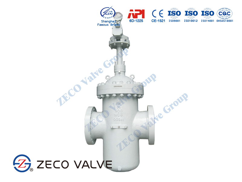
Parallel Expanding Gates
Two slab gates are fitted together in expanding gate valves, which offer to seal by a mechanical expansion of the gate. When the slab gate is lifted, the media can flow through both cavities. The outward mechanical expansion for a proper seal is enabled by the upward force on one slab and the stopping of the second slab by a step in the valve body. When the slab gates are closed, the media flow is stopped, and the downward force (stem) on one slab and the upward force (step in valve body) provide for an adequate seal.
Knife Gates
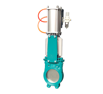
In the case of plastic solids and high-viscosity slurries like paper pulp, a knife gate valve is employed to cut through the material and stop the flow. A knife gate valve has a tapered knife-like edge on its lower surface and is usually not wedge-shaped. Because they pass the seat rings every time they open and close, these valves are self-cleaning.
Isolation valves in block valves in process systems, power plants, and high-temperature valves in refineries all benefit from this seal.
Seat
The gate valve is equipped with two seats that carry out and ensure the seal with the gate. Gate valve seats are either integrated with the valve body or in the form of a seat ring. Seat rings are threaded into position or pressed into position and sealed welded to the valve body in the seat ring construction. For greater temperature service, the latter type of construction is preferred. Integral seats are made of the same material as the valve body, whereas pressed-in or threaded-in seats allow for more variation.
Metal or resilient seats are available for wedge gate valves. A wedge moves towards a groove in the bottom of the gate valve body in metal seated gate valves, trapping particulates contained in the fluid. As a result, resilient seated gate valves are favored in water distribution systems because they enable a tighter shut-off. In resilient seated gate valves, a wedge, often composed of ductile iron, is enclosed in resilient material (elastomer) and therefore forms a tight seal. The seating takes place between the rim of the wedge and the valve body. There is no need for a groove at the bottom of the valve for this. Resistant seated gate valves can thereby seal around tiny solids transported by the water flow.
Stem
The gate is lifted and lowered by spinning a threaded stem. The stem is rotated by a manual wheel or actuator. The stem is classified into two groups, depending on the design:
- Rising stem
- Non-rising stem
Outside Screw and yoke (OS&Y), also known as rising stems, are fixed to the gate. The threads are so on the actuation side. As the gate is elevated or lowered, the stem goes up and down with it. As a result, they contain built-in visual indicators of the valve’s state and are simple to lubricate. They can’t be used with bevel gears or actuators because they have moving components. Hence, rising gate valves are appropriate for manual actuation. In contrast, a non-rising stem is attached to the actuator and threaded into the gate. An indicator is usually threaded onto the stem to display whether the valve is open or closed. For applications with limited vertical space as well as in underground installations, non-rising gate valves are prevalent.
Bonnets
The internal parts of a gate valve are protected by a bonnet. It is bolted or screwed into place on the valve body, forming a leak-proof seal. As a result, it can be removed for repairs or maintenance. Gate valves can have bolt, screw-in, union, or pressure seal bonnets, depending on the application.
Bolted Bonnets
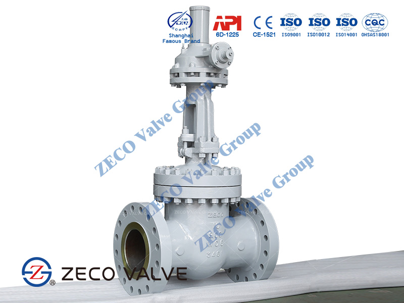
Larger valves and higher-pressure applications require bolted bonnets for sealing. The bonnet and valve body are flanged and bolted together in this design.
Screw-in Bonnets
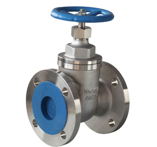
Screw-in bonnets are the simplest to make. They are commonly found in small valves and create a long-lasting leak-proof seal.
Union Bonnets
A union nut keeps union bonnets in place. The union nut rests on the lower edge of the bonnet and screws into the threads of the valve body. This design prevents the leak-proof seal produced by the nut from deteriorating due to repeated bonnet removal. Consequently, union bonnets are frequently used in applications that necessitate routine inspection, repair, or cleaning.
Pressure Seal Bonnets
A pressure seal bonnet is another form of bonnet used in gate valves. This design is used for valves that will be subjected to high pressures, often in excess of 2250 psi (15 MPa). The pressure seal bonnet is distinguished by the fact that it ends in a downward-facing cup that fits inside the valve body. The sides of the cup are pushed outward when the internal pressure in the valve rises, enhancing the body-bonnet seal.
Gate Valve Types
The gate comes in various designs and technologies to produce effective sealing for differing applications.
Knife Gate Valve
A knife gate valve is used for thick fluids and dry bulk solids. The gate is only one piece of metal, which is typically pointed like a knife. These valves are self-cleaning as they pass the seat rings every time they open and close.
Wedge Gate Valve
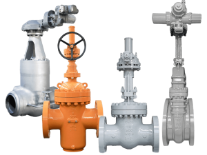
A wedge gate valve has a gate in the shape of a wedge that sits on two inclined seats, as seen in Figure 4 Labeled A. In addition to the primary force created by fluid pressure, a high wedging force on the seats created by the stems tightening assists with the sealing. The wedge-shaped gate does not stick to the seat in case of high fluid differential pressure and has an increased service life due to less “rubbing” on the seats. However, wedge-shaped gate valves have an additional compression load on the seats that may result in thermal binding and restricted valve opening due to expansion.
Parallel Slide Gate Valve
A parallel slide gate valve has a flat gate and seats parallel to it. Parallel slide gate valves use line pressure and positioning to make a tight seal. Flat gates consist of two pieces and have a spring in the middle. The spring pushes the pieces towards the seats for enhanced sealing. Due to their inherent design, parallel gate valves have a safety advantage in higher temperature applications. Furthermore, since there is no wedging action in parallel gates, closing torques are comparatively smaller, resulting in smaller, less expensive actuators or less manual effort. Due to their sliding into position, parallel gates keep dirt away from the seating surfaces.
Slab Gate Valve
Slab gates, also called through-conduit gate valves, are one-unit gates that include a bore-size hole. The bore is in line with the two-seat rings in the open state. This alignment creates a smooth flow with minimal turbulence. This unique design allows for minimal pressure loss in the system and is perfect for the transportation of crude oil and natural gas liquids (NGLs). The valve seats remain clean. However, the disc cavity can capture foreign material. Therefore, the cavity typically has a built-in plug for maintenance purposes of draining the accumulated foreign material.
Where are Gate Valves Used?
Gate valves are often used when minimum pressure loss and a free bore are needed. When fully open, a typical gate valve has no obstruction in the flow path resulting in a very low-pressure loss, and this design makes it possible to use a pipe-cleaning pig. A gate valve is a multiturn valve meaning that the operation of the valve is done by means of a threaded stem. As the valve has to turn multiple times to go from open to the closed position, the slow operation also prevents water hammer effects.
Gate valves can be used for a vast number of fluids. ZECO Gate valves are suitable under the following working conditions:
- Oil and gas pipelines
- Pipeline and storage equipment for refined oil
- Oil and gas mining wellhead facilities
- Intercity gas transmission pipelines
- Tap water and sewage treatment project
How do you Open Gate Valve?
The proper way to open a gate valve is to gently turn the handle counter-clockwise (to the left) without applying excessive force – do not ‘jerk’ the handle. A typical 1″ main control valve for a water line will take about six full turns to fully open. Stop turning as soon as there is any resistance.
Advantages of Gate Valve
It has low flow resistance. The wetted area of the valve body is straight-through, the medium flows in a straight line, hence the flow resistance is small.
- Effortless when opening and closing the gate valve. Whether it is open or closed, the movement direction of the gate is perpendicular to the flow direction of the medium
- The medium can flow in any direction on both sides, easy to install. The gate valve bore is symmetrical on both sides.
- The end-to-end dimension (the distance between the two connecting end faces of the shell) is short
- The gate valve shape is simple, the end-to-end dimension is short, the manufacturing process is good, and the application range is wide.
Disadvantages of Gate Valve
- Erosion and scratches are easily formed between the sealing surfaces, and maintenance is difficult.
- The external dimensions are large, a certain space is required for opening, and the opening and closing time is long
- Stem packing is easily exposed.
If you are looking for reliable motorized gate valve suppliers, please choose ZECO Valve. We will provide you with high-quality products and services!

