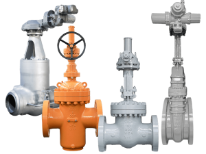
All valves are designed to stop, allow, or throttle the flow of a process fluid. Gate valves—one of the original valve designs—are ideally suited for on-off, primarily liquid, service. A gate valve functions by lifting a rectangular or circular gate out of the path of the fluid. When the valve is fully open, gate valves are full bore, meaning there is nothing to obstruct the flow because the gate and pipeline diameter have the same opening. This bore diameter also determines the valve size. An advantage of this full bore design is very low friction loss, which saves energy and reduces the total cost of ownership.
What Is a Gate Valve?
The gate valve is a member of the linear industrial valve family designed to stop or allow media flow. This valve is bi-directional with a wedge-like disc that can cut through media with thicker particles such as the slurry. The shutoff action is provided by moving the wedge upwards to open or downwards to close the valve.
As with most shut-off valves, the gate valve is not recommended to use for throttling although it has the capacity to do so, albeit limited. Its wedge gate is highly prone to damage caused by the vibration of the moving media.
How do Gate Valves Work?
The opening and closing part of a gate valve is the gate, the movement direction of the gate is perpendicular to the direction of the fluid, gate valve can only be fully open and fully closed, and can not be adjusted and throttled.
The gate has two sealing surfaces. The two sealing surfaces of the most commonly used gate valves form a wedge shape. The wedge angle varies with the valve parameters, usually 5 °, and 2 ° 52 ‘when the medium temperature is not high. The gate of the wedge gate valve can be made into a whole, called a rigid gate; it can also be made into a gate that can produce a small amount of deformation to improve its processability and make up for the deviation of the sealing surface angle during processing. The plate is called a spring gate.
When the gate valve is closed, the sealing surface can be sealed only by the pressure of the medium, that is, the sealing surface of the gate is pressed against the valve seat on the other side to ensure the sealing of the sealing surface, which is self-sealing.
Most gate valves are forcedly sealed, that is, when the valve is closed, the gate is forced to be pressed against the valve seat by an external force to ensure the tightness of the sealing surface. The gate of the gate valve moves linearly with the valve stem, which is called a lift lever gate valve, also known as an open lever gate valve. Usually, there is a trapezoidal thread on the lifting rod. The nut at the top of the valve and the guide groove on the valve body change the rotary motion into a linear motion, that is, the operating torque is changed to the operating thrust. When the valve is opened, when the lift height of the gate is equal to 1: 1 of the valve diameter of the valve, the fluid channel is completely unblocked, but this position cannot be monitored during operation. In actual use, the apex of the valve stem is used as a mark, that is, the position that cannot be opened, as its fully open position. In order to consider the lock-up phenomenon due to temperature changes, it is usually opened to the top position, and then back to 1/2-1 turn, as the position of the fully open valve. Therefore, the fully open position of the valve is determined by the position of the shutter, that is, the stroke. In some gate valves, the stem nut is set on the gate plate. The hand wheel rotates to drive the valve stem to rotate, and the gate plate is lifted. This kind of valve is called a rotary lever gate valve, or a dark lever gate valve.
Gate valve Operation
A gate valve operates similar to other valves. To open the valve, turn the handwheel (A), which moves the gate (G) up or down on the stem (B) via the threads. A gate valve requires more than one 360° turn to open or close the valve fully. When the gate is lifted up, it opens the inlet to the outlet allowing an unobstructed passageway for the media to flow. When the gate is lowered, it closes and blocks the media flow.
The relationship between the gate’s vertical travel and the flow rate is nonlinear for a gate valve, with the greatest changes occurring near-complete closure. When used to regulate flow, the relatively high velocity of the flow at partial opening results in gate and seat wear, which along with possible vibrations of the gate, shortens the valve’s service life. Therefore, a gate valve should only be used for on/off control.
Gate valve Actuation Method
There are three main types of gate valve actuation methods:
Manual gate valve: A manual gate valve has a manually spun handwheel to open or close the valve, as shown in Figure 3. This requires a user on-site to spin the wheel. A manual gate valve is the most economical, especially since the usage of gate valves once installed is typically low.
Pneumatic gate valve: A pneumatic gate valve uses a pneumatic actuator instead of a handwheel. By utilizing compressed air, the actuator can spin the stem to raise or lower the gate. This allows it to be operated remotely with no user on-site but requires a pneumatic system on site.
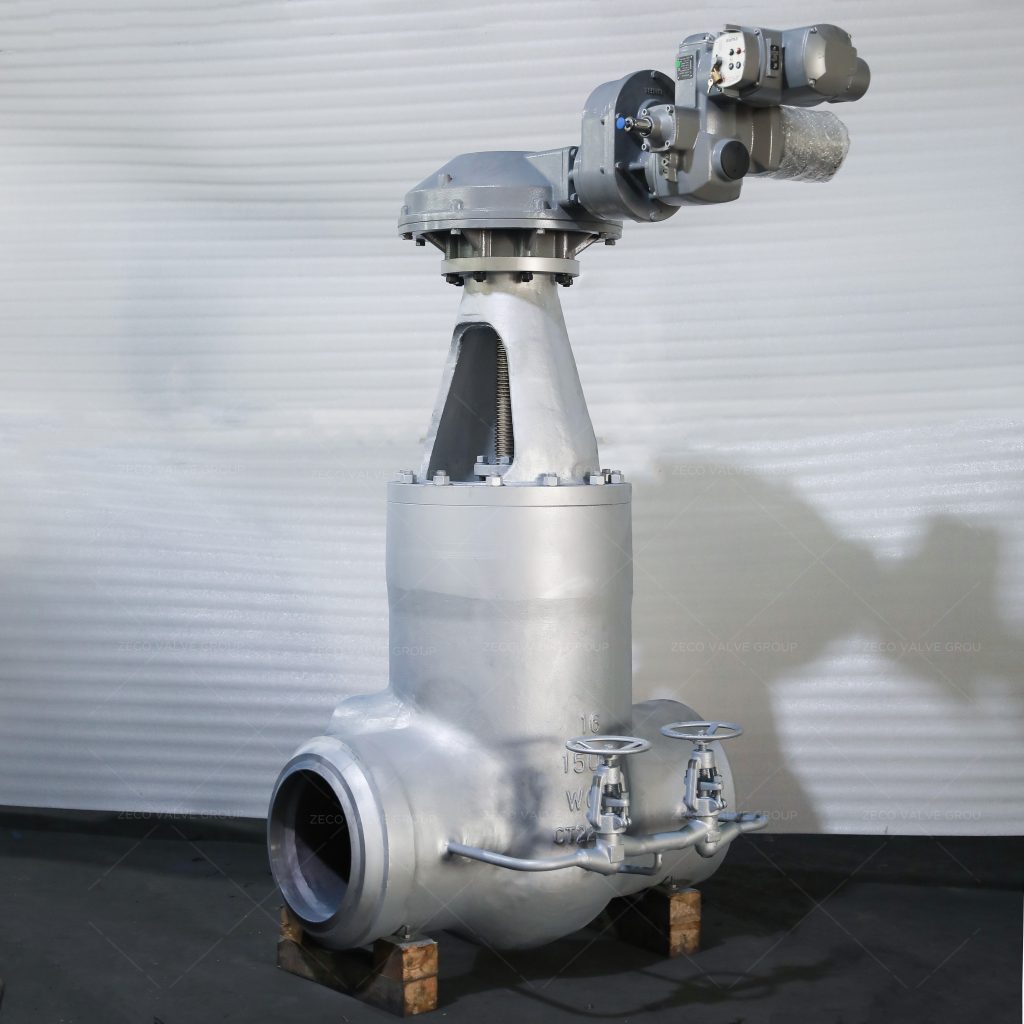
Electric gate valve: An electric gate valve uses an electric motor instead of a handwheel. By utilizing electrical power, the actuator spins the stem to raise or lower the gate. This allows it to be operated remotely with no user on-site but requires electrical power on-site. These are also referred to as motorized gate valve
Gate Valve Movement
When the gate valve is closed, the sealing surface can be sealed only by the medium pressure, that is, only by the pressure of the medium z41h flange wedge gate valve. . Most gate valves are forcibly sealed, that is, when the valve is closed, the gate is forced to be pressed against the valve seat by external force to ensure the tightness of the sealing surface. Movement mode: The gate of the gate valve moves linearly with the valve stem, also known as the open-rod gate valve. There is usually a trapezoidal thread on the lifting rod. The nut at the top of the valve [] and the guide groove on the valve body change the rotary motion into linear motion, that is, the operating torque is changed to the operating thrust. When the valve is opened, when the lift height of the gate is equal to 1: 1 of the valve diameter, the fluid channel is completely clear, but this position cannot be monitored during operation. In order to consider the lock-up phenomenon due to temperature changes, it is usually opened to the top position, and then back to 1/2-1 turn, as the position of the fully open valve. Therefore, the fully open position of the valve is determined according to the position of the gate (ie, the stroke>. Some gate valve stem nuts are located on the gate, and the handwheel rotates to drive the valve stem to rotate, and the gate is lifted. It is called a rotary lever gate valve or a dark lever gate valve.
Related Tags :
Ten articles before and after
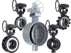
What Are the Types of Butterfly Valves?
Common Fault Judgment and Treatment Method of Pneumatic Ball Valve
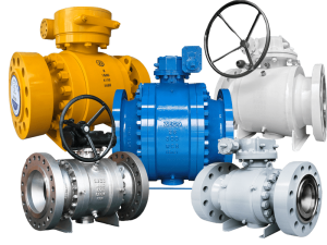
What Do You Need to Know about Pneumatic Ball Valves?
6 Factors Causing the Failure of the Pneumatic Ball Valve Body
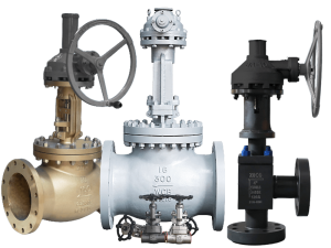
Advantages and Disadvantages of Cast Steel Globe Valve
What Are The Advantages Of The Ball Check Valve?